Repairing errors in JPEG data stream using the Byte Editor
- If you find it easier to learn by watching someone, I still recommend you to read the following, but I also made a narrated video of about 30 minutes.
- Before patching JPEGs you may need to calibrate the magnifier cross-hair. It’s only a few seconds work and explained in this video.
There are two things you can do with the ‘patcher’ or the byte-editor:
- Remove bytes or MCUs from JPEG bit-stream
- Insert bytes or MCUs into JPEG bit-stream
You can do the same with any hex or binary editor but JPEG-Repair makes this a whole lot easier. As data in the JPEG bit-stream is encoded and compressed in small groups of pixels (called MCU’s), one MCU may take up 4 bytes while another 16 bytes. Due to this you will never be able to tell if a pixel at x, y corresponds with any specific data in the bit-stream unless you decode it first.
One MCU is a block of either 8 x 8, 8 x 16 or 16 x 16 pixels. JPEG-Repair ‘decodes’ the JPEG data so clicking that the displayed image selects the correct raw data. So that’s where using JPEG-Repair is more convenient than using a hex editor in combination with a photo viewer. But in essence JPEG-Repair is just that. Apart from working at byte level, JPEG-Repair feature a MCU editor which is more precise than the byte editor. It allows you to fine tune things.
Repairing visually distorted and corrupt JPEG files is pretty much a matter of deleting the corrupt data. As JPEG’s are decoded left to right, scan-line by scan-line, top to bottom the image data following the deleted data will tend to shift to the left. To counter that the next step is adding data to the bit-stream. So rather than editing an image as you would do in a photo editor, we will be deleting from, and adding to the raw file data.
You can clearly see how data is organized in blocks of 8×8 pixels
Generic steps for repair:
Using JPEG-Repair you can experiment with removing, adding and changing bytes while the program provides you with visual feedback. So simply put, you will be (1) picking a point at start of visible corruption, (2) remove corrupt data and (3) insert data to re-align image data.
Up on loading the file JPEG-Repair will automatically remove data that is invalid according to the JPEG specification. Such data frequently prevents the image from rendering or stops rendering from a certain point (half grey pictures). JPEG-Repair may need several iterations of saving and reloading the file.
The editor controls explained
As we need to be able to pick the spot we want to remove and add data from, add data and remove data JPEG-Repair offers some controls allowing us to do so:
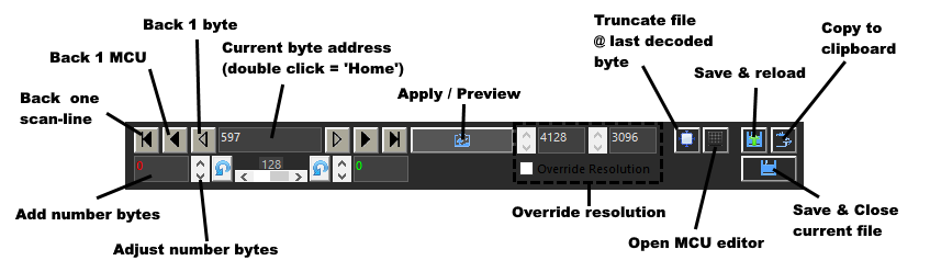
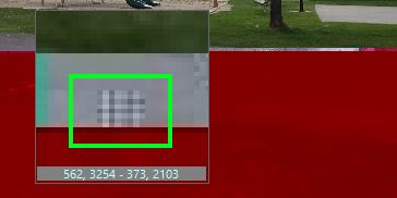
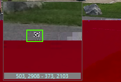
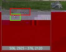
- Select byte address: You do this by double-clicking on the image, preferably right in front of the corrupt data. You can use the arrow keys to move one byte, one MCU or a line of MCU’s. In below example the green box shows the first corrupt MCU. The second shows new corruption because I clicked too high, use the arrow key to move an entire line of MCU’s down ( >| ).
Just clicking the image is not enough to show ‘where we are’, we actually need to remove some data to see where the effect appears in the picture, say 64 or if you see no effect, 128 bytes. - Next step is to remove bytes until all corruption is gone.
- The we will add bytes to re-align image data
An example
Note that there is even more complex damage and corruption I have repaired using JPEG-Repair which I address mostly in videos on my Youtube channel. On this page we cover the basics. We will repair this file:

large part at bottom of photo is grey
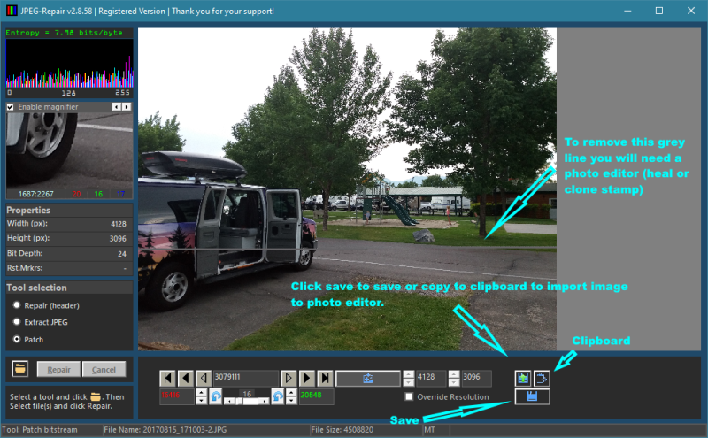
Select the Patch tool, the click the button with the folder icon and select the file. Click Repair. JPEG-Repair will reload the file a few times and remove invalid data. It will give us this:
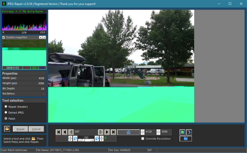
We can already see there is actually data where the grey box was. Now double-click as close as possible to the first corrupt MCU. You can use the magnifier for a closer look. If you press the left mouse button the magnifier will position itself next to the mouse-pointer, if you release the mouse button it will snap back in place. Now use the up and down button next to the red value and remove some bytes. I always start with 64 or 128. The higher the resolution, the more bytes you need to remove to see the effect. Then click apply.
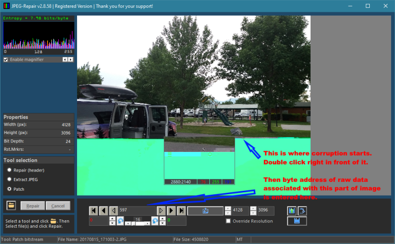
Keep removing corruption by increasing the byte value. You need to click apply to see the effect. So remove a few hundred, click apply. Some times you need to remove thousands of bytes like in this case. You can use the horizontal slider to increase/decrease the step size of the up/down buttons.
Keep going until all corrupt data is removed and you’ll get something like below. See how the bottom part of the image moved to the left due to use removing data. Now start increasing the green value to add (zero or stuff) bytes. It will shift the bottom part to the right. If you double click the green number it will automatically enter the value of removed bytes. Click Apply.

Finally we have something like this. Note that the grey line is a result of the data we added to replace the corrupt data. This is a side effect that can not be avoided and will need to be repaired using a photo editor (heal tool or clone stamp tool) or an inpaint program.
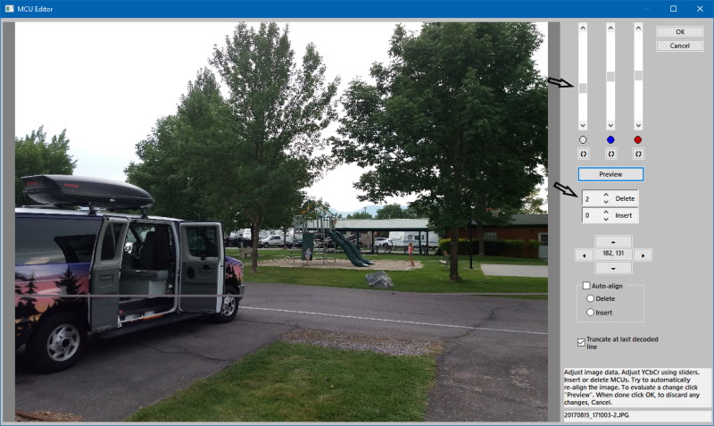
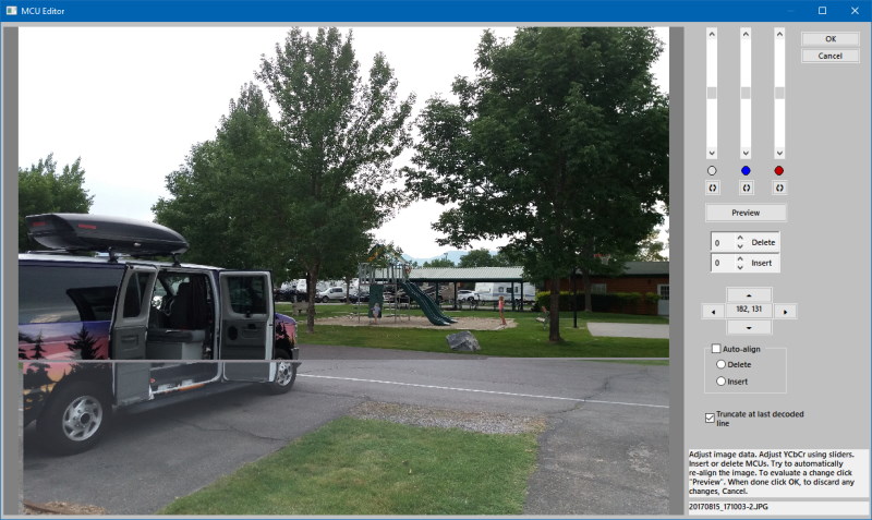
MCU Editor
The byte editor is great for removing larger amounts of corrupt data. However it is not always possible to enter the right amount to perfectly align the image parts or to get the color in area above and below the corruption to match.
The MCU editor follows same method as the byte editor but now everything is MCU based. So rather than show a byte address, the tool shows the MCU coordinates. And rather than travel one byte to the left and right or up and down, you move per MCU. It allows for more precise editing.
You can only run the MCU editor if there are no pending changes. First click Save & Reload if there are any. Double click at the spot where corruption starts or where alignment and/or colors or brightness start ‘shifting’. Now click the MCU edit button.
We see:
- Image data is not aligned properly, it shifts towards the right. It means we need to remove one or more MCUs. So increase that number using up/down arrows and click Preview. Once aligned we need to:
- Adjust color/brightness using the sliders. In this case mostly brightness adjustment is required. Slightly modify the brightness and click Preview. Observe and make further changes as needed.
Click OK if the image looks okay. This will take you back to byte editor, you now can save your changes.